ASES – Australia
Unit 8,
5-7 Wiltshire Street,
MINTO, NSW, 2566, Australia
Phone: +61 2 9933 4900

Email Information:
Sales:
info@ases.co
Support:
support@ases.co
Accounts:
accounts@ases.co
General:
info@ases.co

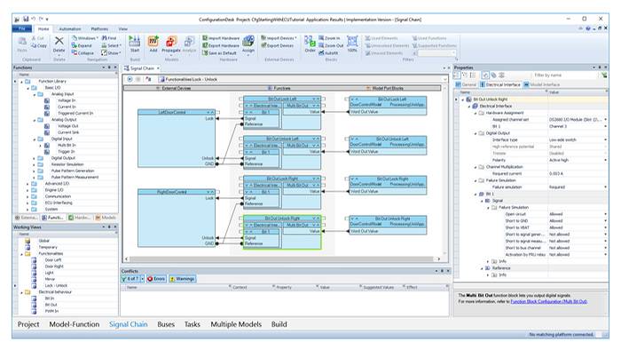
ConfigurationDesk is an intuitive, graphical configuration and implementation tool for SCALEXIO hardware. With this software, you can connect your behavior models from MATLAB®/Simulink®/Simulink Coder™ to I/O functions, for example, configure the SCALEXIO hardware, and control the whole process for generation of real-time code. You can optionally define and document external devices such as ECUs and loads, including their signal properties (descriptions, electrical properties, failure simulation settings, and load settings). ConfigurationDesk offers different views on the configured system. It is possible to display the signal path between the ECU pins/load pins and the behavior model. In other views, you can directly add the I/O functionality to the model hierarchy and propagate interface changes to the connected MATLAB® Simulink® model.
With ConfigurationDesk, you can easily implement the behavior model code and the I/O function code from ConfigurationDesk on the dSPACE real-time hardware. The entire build process for a real-time application is handled by ConfigurationDesk. Besides being able to interactively work with MATLAB Simulink models, you can import previously generated C code from different modeling tools, such as code from the Simulink Coder via Simulink Implementation Containers (SICs) or code from other modeling tools via Functional Mock-up Units (FMUs). Comprehensive documentation options and graphical displays give you great project transparency. You can assemble and configure the project-specific hardware offline as a virtual system, in other words, as a purely software-based configuration. A real-time application can be executed for test runs even if parts of the necessary and configured I/O hardware are not physically available. In addition, there are options to generate a Microsoft® Excel® file with information on the wiring harness and on external devices.
The ConfigurationDesk navigation bar offers task-specific view sets that are optimized for the chosen workflow. Each view displays only the functions required for the respective task. If needed, you can switch between the views while working. Besides being able to interactively work with MATLAB Simulink models, you can import already generated C code via Simulink Implementation Containers (SICs) or code from other modeling tools via Functional Mock-up Units (FMUs). Using model containers reduces external dependencies, because no model tool installation is required to use the models. It also simplifies the exchange and reuse of models, because it saves code generation and build time.
Support of Simulink Implementation Containers
Support of Functional Mock-up Units
Optimized view sets for two different working methods:
To make exchanging simulation models easy, dSPACE offers a Model Interface Package for Simulink® (MIPS) for generating Simulink implementation container (SIC) files.
With the free-of-charge MIPS, modeling experts can generate the (C code) SIC file with Simulink Coder, without needing a VEOS or ConfigurationDesk license. Out of their Simulink models and together with dSPACE Run-Time Target, they can generate code and create ZIP files that contain all the necessary code and artifacts for executing the models on different simulation platforms, such as VEOS and SCALEXIO.
Model integrators using SIC files do not have to generate code again for building the simulation. Using SICs therefore significantly reduces the amount of time needed for reusing the SICs in different projects.
| Functionality | Description |
| General | Graphical configuration of real-time applications |
| Decoupling of I/O configuration and behavior model | |
| Integration of models from various tools | |
| Enhanced graphical User Guidance through the workflow of the Configuration | |
| Simulink support | Generate a ConfigurationDesk project directly from the Simulink model |
| Switch from Simulink to ConfigurationDesk and vice versa | |
| Changes to the interfaces made with ConfigurationDesk can be propagated to the respective Simulink model | |
| Start the overall build process from the Simulink model | |
| FMI support | Support of the open Functional Mock-up Interface (FMI) standard |
| Profit from different modeling approaches (e.g., based on physical modeling with Modelica) by using Functional | |
| Mock-up Units (FMUs) | |
| Integrate FMUs together with Simulink® models. | |
| I/O configuration and documentation | I/O configuration for connecting behavior models to dSPACE real-time hardware (SCALEXIO and MicroAutoBox III): |
| External device topologies (properties of ECU pins and load pins) | |
| Device port mapping (connections between the ECU/load pins and the signal ports of an I/O function) | |
| I/O functions (define and configure the functionality of the assigned real-time hardware) | |
| Model port mapping (connections between function ports and model ports) | |
| Model topology (model ports used for the ConfigurationDesk application) | |
| Hardware resource assignment (mapping of I/O functions to hardware resources) | |
| Hardware topology (hardware resources used by I/O functions) | |
| Documentation options: | |
| External device topologies (properties of ECU pins/load pins) | |
| Model topology (describes the interface to the behavior model) | |
| Hardware topology (describes the simulator hardware: boards, internal wiring, internal loads, board locations, etc.) | |
| Microsoft® Excel® file with pin information for external wiring harnesses | |
| Real-time code generation | Complete build process for I/O functions (ConfigurationDesk) and the behavior model (e.g., MATLAB®/Simulink®/Simulink Coder) |
| Bus simulation | Import of bus configurations as bus configuration containers generated by the dSPACE Bus Manager |
| CAN and LIN signals can be configured either with the Bus Manager or with the RTI CAN MultiMessage Blockset and the RTI LIN MultiMessage Blockset. FlexRay nodes are configured with the dSPACE FlexRay Configuration Package | |
| Ethernet UDP/TCP is supported by dedicated function blocks in ConfigurationDesk | |
| Ethernet SOME/IP is supported by the Ethernet Configuration Package |